Page 42 of 47

Re: FPV backpack PCB build

PostPosted: Wed Nov 20, 2013 10:11 am
by suxi
I think we discussed this before, but I just caught myself again building antennas for the wrong frequency.

The SDS Hobby modules use a "positive logic" (I don't know what the exact english term is) when describing 1 or 0. 1 means a voltage is at the pin, which means no jumper or connection. 0 means no voltage, thus pin is shortened to ground.

Looking at their channel mapping:

Image

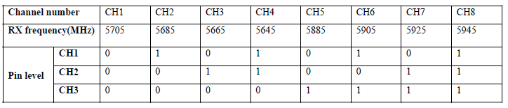
This translates to 5945MHz having no connection at all or all dip switches being open.

Please be aware of this when sourcing your antennas.

Best ...

suxi

Re: FPV backpack PCB build

PostPosted: Thu Nov 21, 2013 11:51 pm
by .j.
Hello i am wanitng to biuld a fpv set and am wondering if these modules will work

reciever
http://www.banggood.com/FPV-5_8G-Wirele ... 84775.html

transmitter
http://www.banggood.com/FPV-5_8G-200mW- ... 84780.html

Re: FPV backpack PCB build

PostPosted: Fri Nov 22, 2013 12:37 am
by TimJC
.j. wrote:Hello i am wanitng to biuld a fpv set and am wondering if these modules will work

reciever
http://www.banggood.com/FPV-5_8G-Wirele ... 84775.html

transmitter
http://www.banggood.com/FPV-5_8G-200mW- ... 84780.html

Those are the correct model modules. Just make sure they support the same channels.

Re: FPV backpack PCB build

PostPosted: Fri Nov 22, 2013 1:47 am
by .j.
thanks on the specifications it says 3.5-5.5v should i still use the 3.3v recomended

Re: FPV backpack PCB build

PostPosted: Fri Nov 22, 2013 3:20 am
by TimJC
There has been some discussion on this, but the ones I bought last year definitely run on 3v3.

To be honest, unless you are building this for fun, it won't be saving you much if any money doing it yourself.

Re: FPV backpack PCB build

PostPosted: Fri Nov 22, 2013 3:53 am
by .j.
thanks i found that the reciver price droped to $9.60 when added to cart so i thought i may give it a try as well as it also working out cheaper when i added the things i would need tgether.

Re: FPV backpack PCB build

PostPosted: Fri Dec 13, 2013 1:40 pm
by michaelogri
Can anyone help, more likely very simple Yes or No.

Have at long last completed two pairs of 5.8GHz TX & RX as per TimJC borads and parts list.
Now is the time to test them.

Can I simply connect the SMAs with coaxial and then work out the matching frequency, once found make correct sized aerials to match the slected frequency?

Also if anyone is interested I have spare made up boards (to the point to faciliate soldering of the TX or RX module) with the remaining components to complete. Will sell at COST! I am in the UK!

Re: FPV backpack PCB build

PostPosted: Fri Dec 13, 2013 5:35 pm
by TimJC
I would construct the antennas for 5800 mHz first. They do not need to be perfectly matched, but you do want to be in the ballpark. You do not want to power up the video TX without an antenna.

If you are looking for a quick and dirty solution, you can make a sleeved 1/2 wave dipole out of the coax. Bruce did this for his FPV Ladybird video. This is done by stripping the plastic insulation off the last ~12.25mm of the coax cable, folding the braided shielding back down over the insulated cable, and leaving the insulated center protruding out the end. That length is an estimate based on IBCrazy's dipole calculations.

Re: FPV backpack PCB build

PostPosted: Sat Dec 14, 2013 10:02 pm
by michaelogri
Thanks
Have made dirty aerials.
:shock:
Will be testing, thanks for the warning about firing TX with NO aerial, I had assummed so much as using 2.4GHz system, as a newby, everyone warns me DAILY!!!!! Or at least when I show!
:lol:

Re: FPV backpack PCB build

PostPosted: Wed Jan 01, 2014 11:50 pm
by CianH
michaelogri wrote:Also if anyone is interested I have spare made up boards (to the point to faciliate soldering of the TX or RX module) with the remaining components to complete. Will sell at COST! I am in the UK!


michaelogri how much would the boards be? Im in the process of looking for a PCB manufacturer but if you have some for sell that would be great!!.


Cian