Hi there,
I got this reply from Himodel. Hope the info is useful.
''The factory did not recall this item, also not all transmitters need to make any change, only very rare types of transmitter which have a unusual high PPM output is suggested to add a diode to reduce the output voltage, the types listed below are confirmed with standard output, and no need to make any change:
Transmitter Module is compatible with the following transmitters:
Futaba module: Futaba: 3PK, 3PM, 7U, 8U, 8J, 9C, 9Z, 10C and FN series.
Hitec: Optic 6, Eclipse 7.
WFLY: WFT09, WFT 08.
JR:347/388/783/U8/PCM10/PCM10S/PCM10SX/ PCM10IIS/8103/J9303/MX-22/MX-24S/PX/9XII
For transmitter types listed above do not need this part, only some special type radios (very rare on market) which the single output is different to conventional radios need this part)
Put it simpler, some types of transmitter (some un-popular brands) have a higher voltage in the signal output, to avoid over voltage/current of the module, they add a diode to reduce the signal voltage, that is all, also, if your transmitter is not the standard output, then it may even affect the function of the module if you add this diode to it, as the signal is reduced once add that part.
Also, the diode is a very popular and common part, normally cost about 0.01USD each, and can be found on any electronic components market, the type of the diode the factory provide is 1N5819, also you can use types BAT85, BAT54 or SS14, etc. (or any other types similar to the mentioned types)
For wiring diagram, refer to http://www.himodel.com/en/service/uploa ... 2971_1.bmp ''
FrSky issues recommended "fix" for DIY kit
42 posts
• Page 2 of 5 • 1, 2, 3, 4, 5
Re: FrSky issues recommended "fix" for DIY kit
![]() by k20a » Wed Aug 25, 2010 5:19 am
by k20a » Wed Aug 25, 2010 5:19 am
- k20a
- Posts: 2
- Joined: Sat May 08, 2010 3:50 pm
Re: FrSky issues recommended "fix" for DIY kit
![]() by RCModelReviews » Wed Aug 25, 2010 8:53 am
by RCModelReviews » Wed Aug 25, 2010 8:53 am
Yes, it seems as if it's only the DIY kit installations (where FrSky has no idea just what part of the transmitter circuitry they'll be connected to) that are affected -- the modules that go into module-based transmitters seem fine.
RCModelReviews.com, just the facts.
-

RCModelReviews - Posts: 2120
- Joined: Tue May 04, 2010 3:40 am
Re: FrSky issues recommended "fix" for DIY kit
![]() by tommy » Wed Aug 25, 2010 11:11 am
by tommy » Wed Aug 25, 2010 11:11 am
Thank you for the info k20a.
I am not familiar with all the radios you have listed.
I have looked at the list of radios you have provided and have noticed some of them are module-based.
Please correct me of I am wrong. From what I understand is that most module-based radios do not need the mod because their output is OC.
Non module based radios where you use the DIY kit ( V8HT) will need the mod. I.e my jr xp 662.
Unfortunately I don’t have the equipment to test the ppm output of my radio
- tommy
- Posts: 39
- Joined: Sat Jun 19, 2010 9:46 am
Re: FrSky issues recommended "fix" for DIY kit
![]() by RCModelReviews » Wed Aug 25, 2010 10:44 pm
by RCModelReviews » Wed Aug 25, 2010 10:44 pm
As I understand it, module-based radios aren't affected -- It is simply the DIY kit were the PPM input may be connected to part of the circuit that delivers more voltage than the microcontroller is designed to handle.
With the Corona DIY, I have built small transistor buffers in the past to overcome this same problem.
With the Corona DIY, I have built small transistor buffers in the past to overcome this same problem.
RCModelReviews.com, just the facts.
-
RCModelReviews - Posts: 2120
- Joined: Tue May 04, 2010 3:40 am
Re: FrSky issues recommended "fix" for DIY kit
![]() by erezra » Thu Aug 26, 2010 10:50 am
by erezra » Thu Aug 26, 2010 10:50 am
So basically if I connected my DIY kit to the PPM leg of the MODULE output on my 9x I should be fine without the diode? Or should I install the module just to be safe?
!!! BEWARE - WE ARE IN THE AIR !!!
http://www.eraviv.com
http://www.eraviv.com
- erezra
- Posts: 37
- Joined: Fri Jun 25, 2010 7:10 pm
Re: FrSky issues recommended "fix" for DIY kit
![]() by tommy » Thu Aug 26, 2010 10:35 pm
by tommy » Thu Aug 26, 2010 10:35 pm
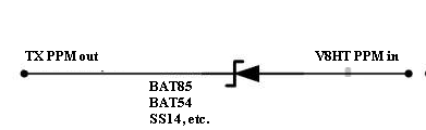
- fix.JPG (9.79 KiB) Viewed 17431 times
This is the fix that I have seen. I was wondering if you could please explain how this works.
I have a basic understanding ( I know about pull up and down transmitters, diodes ohms law etc...)
I just think I need a basic explanation of what happen when a ppm singnal is introduced into the circuit.
I have also read that this solution may not be ideal because
Quote
Personally I would not use this option if you are someone who hot-plugs modules or have a setup where the 0V connection could be lost, or are prone to mis-wire things!
Where will the current will go if the + rail and PPM are connected without 0V.... pop goes the microcontroller input. Or pop goes the open collector/logic driver first? A good design would protect both microcontroller input protection diodes, i.e. the one to +rail and the -rail.
Thank you.
- tommy
- Posts: 39
- Joined: Sat Jun 19, 2010 9:46 am
Re: FrSky issues recommended "fix" for DIY kit
![]() by RCModelReviews » Thu Aug 26, 2010 11:07 pm
by RCModelReviews » Thu Aug 26, 2010 11:07 pm
The stuff in the right hand square represents the bits that are already in the DIY kit an this mod simply involves the addition of a single diode that will effectively stop any voltage greater than 3V from reaching the DIY board.
If you were to connect the PPM line to +12V, the DIY board would still only see 3V because the diode that's added effectively blocks the voltage from flowing into the board.
However, when the PPM input voltage drops to below 3V, the diode allows the input to the DIY module to fall in concert with that PPM voltage -- so you end up getting a PPM signal that is 0-3V , which is what it should be.
The diode actually imposes a small "potential barrier" so the input voltage the module saw would actually be 0.2V-3V but for all intents and purposes, the 0.2V is the same as 0V.
It's a simple but effective fix.
RCModelReviews.com, just the facts.
-
RCModelReviews - Posts: 2120
- Joined: Tue May 04, 2010 3:40 am
Re: FrSky issues recommended "fix" for DIY kit
![]() by tommy » Thu Aug 26, 2010 11:56 pm
by tommy » Thu Aug 26, 2010 11:56 pm
Thank you Bruce.
Seems so simple now.
Thanks again.
Seems so simple now.
Thanks again.
- tommy
- Posts: 39
- Joined: Sat Jun 19, 2010 9:46 am
Re: FrSky issues recommended "fix" for DIY kit
![]() by erezra » Fri Aug 27, 2010 9:59 am
by erezra » Fri Aug 27, 2010 9:59 am
So if you want to limit the voltage you use a Zener diode and not a Schottky diode, right?
Why use a Schottky here?
What am I missing?
Why use a Schottky here?
What am I missing?
!!! BEWARE - WE ARE IN THE AIR !!!
http://www.eraviv.com
http://www.eraviv.com
- erezra
- Posts: 37
- Joined: Fri Jun 25, 2010 7:10 pm
Re: FrSky issues recommended "fix" for DIY kit
![]() by tommy » Fri Aug 27, 2010 11:48 am
by tommy » Fri Aug 27, 2010 11:48 am
Zener doiode is normally used to regulate voltage at a specific value. What we are doing here is blocking any
voltage above (3.3v - potential barrier) from entering circuit. Due to the pull up resistor the diode will only allow current to flow when the ppm voltage falls below (3.3v minus the potential barrier). Hence when the PPM voltage is high (above 3.3v - potential barrier) the DIY moduel will only ever see 3.3V. Also Schottky diode has fast switching and a low potential barrier which makes it better to use than a standard diode. Thats my understanding anyhow.
Hope this helps
- tommy
- Posts: 39
- Joined: Sat Jun 19, 2010 9:46 am
42 posts
• Page 2 of 5 • 1, 2, 3, 4, 5
Return to DIY Projects and Hacks
Who is online
Users browsing this forum: No registered users and 5 guests